What is TCP/IP?
TCP/IP is a set of protocols developed to allow computers to share resources
across a network. It was originally developed by a community of researchers
centered around the ARPAnet which is the best-known TCP/IP network. The most
accurate name for the set of protocols we are describing is the "Internet
protocol suite", TCP and IP are two of these protocols, and it has become common
to use the term TCP/IP to refer to the whole suite.
TCP/IP is a family of
protocols, some provide "low-level" functions needed for many applications.
These include IP, TCP, and UDP. Others are protocols for doing specific tasks,
e.g. transferring files between computers, sending mail, or finding out who is
logged in on another computer. Originally, TCP/IP was used between minicomputers
or mainframes, which had their own disks and were self-contained.
The
most important TCP/IP services are:
File Transfer Protocol (FTP) allows a
user on any computer to transfer files, to or from, another computer. Security
is handled by requiring the user to specify a user name and password, though
some allow ‘anonymous’ connections.
Remote Login, the network terminal
protocol (TELNET) allows a user to log in on any other computer on the network.
A remote session is started by specifying the computer to connect to, and from
that time until the session ends, anything typed is sent to the remote computer.
These connections generally behave like dial-up connections.
SMTP -
Simple Mail Transfer Protocol allows messages to be sent to users on other
computers. Originally, this was restricted to one or two specific computers
which would maintain "mail files". The computer mail system is simply a way for
messages to be added to another user's mail file.
These services are
present in any implementation of TCP/IP and they still play an important role in
TCP/IP based networks. However more recently, the way in which networks are used
has been changing. Although people are still likely to work with one specific
computer, that computer will call on other systems on the net for specialized
services.
This has led to the "server/client" model of network services.
A server is a system that provides a specific service for the rest of the
network. A client is another system that makes use of that service. (The server
and client need not be on different computers, they could be different programs
on the same computer.) Some examples of servers typically present in a modern
computer setup are listed below, they can all be provided within the framework
of TCP/IP.
Network file systems allow a system to access files on another
computer in a more integrated way than FTP. A network file system provides the
illusion that disks or devices from one system are directly connected to
another, and the computer thinks it has extra disk drives. These extra "virtual"
drives actually refer to the other system's disks. This is useful for several
different purposes; It lets you put large disks on a few computers, but giving
others access to the disk space, this allows people on several computers to
share common files; System maintenance and backup is easier, because you don't
have to worry about updating and backing-up copies on lots of different
machines.
Remote printing allows users to access printers on other
computers as if they were directly attached to theirs, and remote execution
allows them to request that a particular program is run on a different computer.
This is useful when some tasks require the resources of a larger
system.
In larger installations, there are a number of different
collections of names that have to be managed. This includes users and passwords,
names and network addresses for computers and accounts. It becomes very tedious
and time consuming keeping all this information up to date on many computers, so
databases of this information are kept on a small number of systems, called
"Name servers", and other systems access the data over the network.
Ethernet Explained
Ethernet is the least expensive high-speed LAN option. Ethernet adapter cards
for a PC transmit and receive data at speeds of 10 million bits per second (10
Mbps) through up to 300 feet of ‘telephone’ wire to a hub. Data is transferred
between hubs using a heavy coaxial cable ("Thicknet"), or a fibre-optic cable.
This heavy coaxial cable is used for medium-long distances where medium levels
of reliability are needed. Fibre optic cable goes further and has greater
reliability, but a higher cost. To connect a number of workstations within the
same room, a light duty coaxial cable called "Thinnet" is used.
Early
development of Ethernet was done by Xerox research and the name "Ethernet" was a
registered trademark of Xerox Corporation. The technology was refined and a
second generation called Ethernet II was widely used. Ethernet from this period
is often called DIX after its corporate sponsors Digital, Intel, and
Xerox.
As the holder of the trademark, Xerox established and published
the standards, however, no technology could become an international standard if
the rules were controlled by a single US corporation, so the IEEE was assigned
the task of developing formal international standards for all Local Area Network
technology. It formed the "802" committee to look at Ethernet, Token Ring, Fibre
Optic, and other LAN technology. The objective of the project was not just to
standardize each LAN individually, but also to establish rules that would be
global to all types of LAN so that data could easily move from Ethernet to Token
Ring or Fibre Optic.
This created conflicts with the existing practice
under the old Xerox DIX system, and the IEEE was careful to separate the new and
old rules. It recognized that there would be a period when old DIX messages and
new IEEE 802 messages would have to coexist on the same LAN. It published a set
of standards of which the most important are:
	802.3 - Hardware standards for Ethernet cards and cables
	802.5 - Hardware standards for Token Ring cards and cables
	802.2 - The new message format for data on any LAN
The 802.3 standard further refined the electrical connection to the
Ethernet and it was immediately adopted by all the hardware vendors. Today all
cards and other devices conform to this standard. However, the 802.2 standard
would require a change to the network architecture of all existing Ethernet
users.
Apple had to change its Ethertalk, and did so when converting from
Phase 1 to Phase 2 Appletalk. DEC had to change its DECNET. Novell added 802 as
an option to its IPX, but it supports both DIX and 802 message formats at the
same time. The TCP/IP protocol used by the Internet wouldn't change, since the
Internet standards are managed by the IETF group, and they decided to keep the
old DIX message format indefinitely. This produced a deadlock between the two
standards organizations which has not been resolved.
This means that
Ethernet suffers from too many standards, the old DIX rules for message format
persist for some uses (Internet, DECNET, some Novell) whilst the new 802 rules
apply to other traffic (SNA, NETBEUI). The most pressing problem is to make sure
that Novell clients and servers are configured to use the same frame format.
Explain Fast Ethernet
Fast Ethernet is an extension of the popular 10BASE-T Ethernet standard, Fast
Ethernet transports data at 100 Mbps. With rules defined by the IEEE 802.3u
standard, Fast Ethernet leverages the familiar Ethernet technology and retains
the CSMA/CD protocol of 10 Mbps Ethernet. There are two types of Fast Ethernet
available; 100BASE-TX, which runs over Category 5 UTP, and 100BASE-FX, which
operates over fibre-optic cable.
What is CSMA/CD?
Access and Collisions Ethernet uses a protocol called CSMACD. This stands for
"Carrier Sense, Multiple Access, Collision Detect". The "Multiple Access" part
means that every station is connected to a single data path. The "Carrier Sense"
part says that before transmitting data, a station checks the data path to see
if any other station is already sending something. If the LAN appears to be
idle, then the station can begin to send data.
An Ethernet station sends
data at a rate of 10 Mbps, that allows 100 nanoseconds per bit. Light and
electricity travel about one foot in a nanosecond therefore, after the electric
signal for the first bit has traveled about 100 feet down the data path, the
station begins to send the second bit. However, an Ethernet cable can run for
hundreds of feet, if two stations are located 250 feet apart on the same path,
and both begin transmitting at the same time, then they will be in the middle of
the third bit before the signal from each reaches the other station.
This
explains the need for the "Collision Detect", two stations can begin to send
data at the same time, and their signals will then "collide". When such a
collision occurs the two stations stop transmitting, "back off", and try again
later after a randomly chosen delay period.
Every set of rules is best
understood by characterizing its worst case. The worst case for Ethernet starts
when a PC at the extreme end of one wire begins sending data, this electric
signal passes down the wire through repeaters, and just before it gets to the
last station at the other end of the LAN, that station (thinking that the LAN is
idle) begins to transmit its own data. A collision occurs and the second station
recognizes this immediately, however, the first station will not detect it until
the collision signal retraces the first path all the way back through the LAN to
its starting point.
Any system based on collision detect must control the
time required for the worst round trip through the LAN. As the term Ethernet is
commonly defined, this round trip is limited to 50 microseconds. At a signaling
speed of 10 Mbps this is enough time to transmit 500 bits, and at 8 bits per
byte this is slightly less than 64 bytes. To make sure the collision is
recognized, Ethernet requires that a station must continue transmitting until
the 50 microsecond period has ended. If the station has less than 64 bytes of
data to send, then it must be padded with trailing zeros.
While an
Ethernet can be built using one common data path, such an arrangement is not
flexible enough to wire most buildings. Unlike an ordinary telephone circuit,
Ethernet wire cannot be just spliced together connecting one copper wire to
another, a repeater is required. A repeater is a simple station that connects
two wires, any data received on one wire is immediately repeated bit- for-bit on
the other wire. It has no memory, does not depend on any protocol, and
duplicates everything, including collisions. Repeaters are commonly used to
convert the Ethernet signal from one type of wire to another, while switches are
used to link several LAN’s.
What are Switches?
Switches are another type of device used to link several separate LANs and
provide packet filtering between them. A LAN switch is a device with multiple
ports, each of which can support a single endstation or an entire Ethernet or
Token Ring LAN. With a different LAN connected to each of the switch's ports, it
can switch packets between LANs as needed. In effect, it acts like a very fast
multiport bridge where packets are filtered by the switch based on the
destination address.
Switches are used to increase performance on an
organization's network by segmenting large networks into many smaller, less
congested LANs, while still providing necessary interconnectivity between them.
Switches increase network performance by providing each port with dedicated
bandwidth, without requiring users to change any existing equipment, such as
NICs, hubs, wiring, or any routers or bridges that are currently in place.
Switches can also support numerous transmissions
simultaneously.
Deploying technology called dedicated LANs is another
advantage of using switches. Each port on an Ethernet switch supports a
dedicated 10 Mbps Ethernet LAN, usually these LANs comprise multiple stations
linked to a 10BASE-T hub, but it is also possible to connect a single high-
performance station, such as a server, to a switch port.
As was noted
earlier, LAN switching is a relatively new technology. Today's switching devices
switch relatively large, variable-length LAN packets between different LANs. ATM
is another type of switching technology that switches small, fixed-length cells
containing data. ATM networks can be run at much higher data rates than today's
LANs. Eventually, they will be used to carry voice, video, and multimedia
traffic, as well as computer-generated data over both short and long distances.
ATM will be one of the dominant enterprise networking technologies of the
future, and many companies are beginning to develop strategies to incorporate
ATM in their existing LANs and LAN internetworks.
What is Ethernet
Switching?
Ethernet switching is a sub-category of intelligent switching hubs for other
protocols, such as Token Ring and FDDI, but the term has been vaguely used over
the years. The hardware variations are:
Port switches: All the traffic
from one port can be assigned to one of the separate backplanes via a software
switch. These are used to segment a large network and provide permanent
connections between segments. These switches are more like automatic
patch-panels, they aren't true Ethernet switches in the sense of handling
packets on a packet-by-packet basis, and they can be remotely
managed.
Fast routers: These switches are store-and-forward devices, but
they can give power users a dedicated 10Mb/s rate on a single connection. The
need for hub-buffering slows these systems down to a degree, but being
store-forward, they can handle rate-conversion provided they have the buffer
capability and controls. Some are configured as bridges but most as routers.
Most of these come with 24 or so 10Base-T ports, each of which can provide
10Mb/s to the user, and at least one 100Base-T Fast Ethernet (or other) port for
backbone connections and connection to the server.
Matrixor cut-through
switches: These tend to pass packets through on the fly, and are much faster.
However if many segments are attempting to access a single server, the switch
will respond no faster than a shared network. These are true Ethernet switches
which stream data across cross-connects: the packet's front end leaves the
switch before the back enters. It not possible to change data rate through these
switch since there is no store-forwarding in the conventional
sense.
Hybrids: These are cut-through when they need to be, and
store-forward at other times.
What is a Digital Subscriber
Line?
This is commonly termed ‘xDSL’, which covers a number of similar yet
competing forms of digital subscriber line (DSL) technologies, the ‘x’ is filled
in with another letter, depending on the technology implemented. The major xDSL
categories are;
     Asymmetric Digital Subscriber Line (ADSL)
     High-bit-rate Digital Subscriber Line (HDSL)
     Rate Adaptive Digital Subscriber Line (RADSL)
Each technology offers different speeds, ranges, and operating
characteristics. While there is some overlap in the various technologies, it's
likely that they will coexist in a complementary rather than competitive
fashion. But that leaves service providers in somewhat of a quandary when it
comes to deciding which technology to deploy in the lucrative broadband access
market. This is why it is important to know what each implementation offers.
HDSL Explained
Of all the xDSL offerings, HDSL probably has the largest installed base
because it was the first DSL technology to be invented . The technology arose
from carriers' problems in extending broadband speeds, specifically T1 (1.544
Mbps) and E1 (2.048 Mbps) services, over long copper loops. Because long copper
loops distort signal quality, repeaters or amplifiers are installed on copper
pairs at prescribed intervals to restore signal quality. In today's T1/E1
networks, they must be installed about every 3,000 to 4,000 feet, a time
consuming and expensive process.
In the late 1980s, Bellcore began
research into a new method of T1 and E1 provisioning that would eliminate
repeaters and simplify the overall deployment of high bandwidth networks for the
so-called "last mile" into the home or office. The technology, called HDSL, was
designed to deliver traditional T1/E1 services over unconditioned wires by
placing transceivers on each end of two or three twisted pair.
However,
HDSL is also being modified to work over a single copper phone line to provide
direct premises connections between a customer and its serving central office.
The penalty for operating over one pair is performance; current implementations
are either 384 Kbps or 768 Kbps symmetrical speeds. It is predicted that single
pair HDSL will be an interim development, eventually superceded by ADSL which
provides higher throughput rates.
ADSL Explained
This is the form of DSL that will become most familiar to home and small
business users. ADSL is ‘asymmetric’ because most of its two-way or duplex
bandwidth is devoted to the downstream direction, sending data to the user, only
a small portion of bandwidth is available for upstream. This is an advantage
though, since most Internet and especially multi-media Web data need lots of
downstream bandwidth, whereas user requests and responses are small and require
little upstream bandwidth.
With ADSL, data can be sent downstream at up
to 6.1 Mbps and up to 640 Kbps upstream. The high downstream bandwidth means
that a phone line will be able to bring motion video, audio, and 3-D images to a
computer via a dial-up connection, or a TV set with a special decoder box. In
addition, a small portion of the downstream bandwidth can be devoted to voice
rather data, so that phone conversations can still take place without the need
for a separate phone line.
Individual efforts in creating ADSL produced
two competing algorithms that both offer downstream rates over 6 Mbps with
duplex transmissions of 640 Kbps over single pair lines of 12,000 feet or less.
The first is Discrete Multi-Tone (DMT), which is the established ANSI standard,
and the other is Carrierless Amplitude and Phase modulation (CAP) used as a
side-by- side standard with DMT.
DMT works by dividing the 1 MHz
spectrum, offered by a phone line, into 256 4KHz channels. It then varies the
bit densities on each of these channels to eliminate noise and interference
present in sections of that spectrum. Supporters claim DMT is better on noisy
lines since it has the ability to maximize throughput on good channels and
minimize throughput on channels with noise or interference.
CAP relies on
a single carrier and uses techniques similar to the Quadrature Amplitude
Modulation (QAM) used in V.34 (28.8 Kbps) modems to make the most of phone
lines.
Both algorithms have elicited positive responses from a
performance viewpoint. So if they both perform similarly, cost and manageability
is likely to be the deciding factor between the two. CAP currently leads DMT in
cost and size, but DMT offers greater flexibility. Which method will be
preferred in networks remains to be seen, but most consumers will not know which
is implemented in their modems.
Technically, both DMT and CAP place an
ADSL modem on each end of a twisted-pair phone line, creating three information
channels; a high speed downstream channel; a medium speed duplex channel; and a
POTS (Plain Old Telephone Service) channel.
Referring to figure 1.1, the
POTS channel is split off from the digital modem by filters, this isolates the
voice circuit so it can be powered by a traditional phone line. This allows
uninterrupted POTS connections, even if the ADSL connection or outside power
fails. It also means that service providers can keep voice and data on separate
networks, reducing congestion on the PSTN that is created by transferring data
over circuit-switched rather than packet or cell-switched
connections.
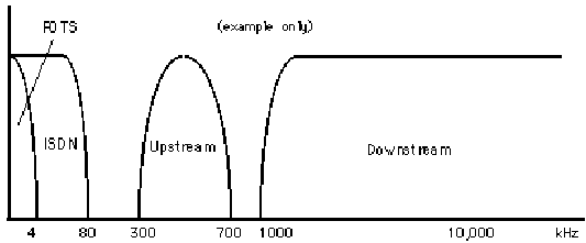
Figure 1.1 -
Frequency Division Multiplexing in xDSL
It is expected that the current
fixed-rate forms of CAP and DMT will evolve into variable rate designs, which
will enable ADSL connections to overcome loop length limitations of 18,000 feet.
DMT designs support variable rates in increments of 32 Kbps whereas CAP designs
currently support 200 Kbps steps.
What is Dense Wavelength Division
Multiplexing?
Dense Wave Division Multiplexing (DWDM) is the technique of passing multiple
frequencies of light simultaneously across a single fibre optic cable, it is
being developed to increase the capacity of optical fibre infrastructures. The
simplest way to understand DWDM is as a large number of virtual fibres that run
from one place to another. The optical signals of the virtual fibre occupy a
portion of the actual fibre's bandwidth.
DWDM allows many channels, each
operating at up to 10Gbps, to be transmitted over the same optical fibre using
different wavelengths. The current recommendation for channel spacing is 100
GHz, and early DWDM systems carried 32 to 40 channels. 64 to 128 channel systems
are now available, and systems supporting over 200 channels have been announced
with advances in cable technology. This represents more than a terabit of
information on a single fibre.
Early DWDM systems were point to point,
but now DWDM rings are being introduced, see figure 1.2.

Figure 1.2 - DWDM Ring
Even
simple DWDM applications require several additional components to construct the
network. The optical inputs for DWDM equipment are specified by the wavelength,
bandwidth, and power;
Typical input wavelengths are 1310 or 1550
nanometers. Data bandwidth varies, DWDM equipment is most efficient when used to
pass SONET, but this is partly due to the amount of SONET equipment in use in
the markets that DWDM is being sold to. Broadband modulators can accept a range
of bandwidth but fall behind SONET rates. Finally, input power specifications
have to cover a large range. This can be done by using amplifiers to boost low
signals, or attenuators where the power level is over the power limit of the
receiver.
Previously, SONET/SDH systems managed the lowest level of the
network infrastructure, but with DWDM, a new optical networking layer has
emerged. This now occupies the bottom network layer, interfacing with the
optical fibres below and providing wavelengths ("lightpaths") to the clients
above. Above the optical network elements there are many systems transmitting
data over wavelengths provided by the optical network layer. These systems can
use circuit, cell, or packet multiplexing depending on the services they deliver
to the clients above.
The capacity of DWDM systems has increased
dramatically in recent years and is expected to continue rising. DWDM is an
important technology for addressing the capacity that will be needed for
Internet and other IP service growth in coming years.
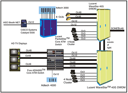
Figure 1.3 - DWDM System (Courtesy Lucent
Systems)
Connecting internetwork equipment directly to DWDM systems
reduces the amount of SONET/SDH equipment in the network. This in turn reduces
the cost of installing and managing high-speed IP backbone links. In the future,
internetworking equipment will use more of the wavelengths provided by DWDM
systems.
Point-to-point DWDM systems are the first step in the use of an
optical transport infrastructure which can deliver more bandwidth than SONET/SDH
networks, at a lower cost. Key to this will be the introduction of optical
add/drop multiplexers and optical cross-connects optimized to switch broadband
channels with far greater capacity than currently available solutions.
What is an add-drop
multiplexer?
A multiplexer/demultiplexer can combine various inputs into a single signal,
with an Add-Drop Multiplexer (ADM) at an add/drop site, only those signals that
need to be accessed are dropped or inserted. The remaining traffic continues
through the network element without requiring special pass-through units or
other signal processing.
For example, one vendor might offer an add/drop
multiplexer with access at E1 only, whereas another might offer simultaneous
access at E1 and E4 rates (see Figure 1.4).
In rural applications, an ADM
can be deployed at any intermediate location to consolidate traffic from widely
separated locations, and this traffic can be any mixture of voice, data, and
video.
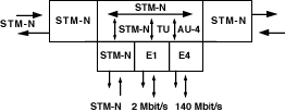
Figure 1.4 - Add/Drop
Multiplexing Sites
What is a Passive Optical Network
(PON)?
The general structure of a PON is shown in Figure 1.5. Its main elements are
the Optical Line Termination (OLT) and a number of Optical Network Units
(ONU).

Figure 1.5 - Structure of a
PON
The OLT is connected to the ONU through the point-to-multipoint PON
that is made up of fibre cables, splitters and other passive components. Up to
32 ONU’s can be connected to an OLT, depending on the splitting factor. The OLTs
are usually located in local exchanges, but the ONUs can be on the streets
(Fibre To The Curb - FTTC), in buildings (Fibre To The Building - FTTB), or in
the users premises (Fibre To The Home - FTTH).
FTTC, and FTTB can both
serve around 250 homes. The best solution depends on the number of the users who
would share the ONU in any setup, the lower the number of users in an area, the
more the FTTC solution may be best.
There are a number of advantages of
PON’s;
1. High bandwidth (up to 622 Mbps downstream and 155 Mbps upstream),
this can be flexibly allocated to the users depending upon their needs.
2.
Improved reliability of data transmission.
3. Suitable for interactive and
distributive services, due to the high bandwidth capacity.
However, there
are also disadvantages;
1. Installation costs are still quite high.
2.
There is a lack of reference standards.
An alternative approach consists
of a combination of a PON network, using multiple wavelength multiplexing, and a
coaxial delivery on existing or new CATV islands, see Figure 1.6.

Figure 1.6 - PON Trunk and Coaxial
Structure
In this model, a CATV network of part fibre, part coaxial is
established. At the fibre part of the network, multiple wavelengths are used
over an APON with a splitting factor of 64, DWDM is used to combine these
wavelengths on one fibre. A number of wavelengths are used for interactive
traffic (spacing 0.8 nm), and another wavelength is used for analogue CATV
distribution.
At the coaxial part, high speed modems will support an
Ethernet interface. The ATM is ended in the ONU and then Ethernet is used. This
provides up to 2 Mbps upstream capacity, so at least 10 Mbps upstream has to be
provided since one ONU serves 12-40 customers.
The advantages of this
system are;
1. Flexibility of the distribution of bandwidth, by using
multiple wavelengths and wavelength switching in the ONU.
2. Total capacity
is divided between the users in an optimal way.
3. The network can cope with
changing capacity demand during the day.
The disadvantages are again the
higher cost of installation and the lack of reference standards.