NETWORK TUTORIAL

Written by Robert Brian Brown

This section discusses the various network components which make up a network. Its discusses cabling types, patch panels, connectors and network components like bridges, routers and ethernet switches.

Brief Guide to BUILDING WIRING
The following is a very brief overview of the components that make up the wiring standards for commercial buildings. The objectives of such standards is to:

  • define a generic voice and data wiring system that is multi-purpose and multi-vendor
  • help minimise cost of administration
  • simplify network maintenance and changes

A building wiring system covers a number of different elements

Horizontal Wiring
The horizontal wiring extends from the wall outlet to the system centre (telecommunications closet). It includes the:
- the wall outlet
- the horizontal cable
- cross-connects or patch cables in the telecommunications closet (TC)

Some general features of the horizontal wiring scheme are:
- uses star topology
- limit of 90 meters (295') from TC to wall outlet
- limit of 3 meters (10') to connect from wall outlet to PC
- patch cords and cross-connect leads are limited to 6 meters (20')
- minimum of two outlets per user (phone+data)
- standardized media, Outlet A=4pair 100ohm UTP, Outlet B=same or 2 pair 150ohm STP

Backbone Wiring
The backbone wiring system interconnects telecommunication closets, equipment rooms and entrance facilities (ie, the outside world). Some general features are:
-star topology
-maximum of two hierarchical levels
-interconnections between any two TC must not go through more than 3 cross connects
-use of recognised media
-adherence to distance limitations


Cabling Types
Twisted Pair (STP and UTP)
-used in token ring (4 or 16MB/s), 10BaseT (Ethernet 10MB/s)
-cheap
-easy to terminate
-UTP often already installed in buldings
-UTP prone to interference
-low to medium capacity
-medium to high loss
-category 3 = 10MB/s, category 5 = 100MB/s

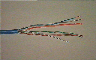
Unshielded Twisted Pair cable used in Category 5 looks like:

Category 5 cable uses 8 wires. The length of exposed wires is very critical, the standard limits this to less than 1/2" an inch. The various jack connectors look like:

The patch cord which connects the workstation to the wall jack looks like:

In 10BaseT, each PC is wired back to a central hub using its own cable. There are limits imposed on the length of drop cable from the PC network card to the jack, the length of the horizontal wiring, and from the jack to the wiring closet.

This is obviously a physical STAR configuration, in that each PC is wired back to a central point (the Hub).
Ethernet 10Base-T wiring specifies an 8 position jack, but uses only two pairs.

TWISTED PAIR ETHERNET HORIZONTAL WIRING (Solid 24Awg)

Pin Colour Signal
1 White/Orange Tx data +
2 Orange/White Tx data -
3 White/Green Rx data +
4 Blue/White --
5 White/Blue --
6 Green/White Rx data -
7 White/Brown --
8 Brown/White --

Each run < 80m from nearest hub

Patch Cables
Patch cables come in two varieties, straight through or reversed. One application of patch cables is for patching between modular patch panels in system centers. These are the straight through variety. Another application is to connect workstation equipment to the wall jack, and these could be eitherstraight through or reversed depending upon the manufacturer.

Reversed cables are normally used for voice systems.

How to determine the type of patch cable
Align the ends of the cable side by side so that the contacts are facing you, then compare the colors from left to right.

If the colors are in the same order on both plugs, the cable is straight through. If the colors appear in the reverse order, the cable is reversed.


Coaxial Cable
-medium capacity
-Ethernet systems (10MB/s) and Arcnet
-slighter dearer than UTP
-more difficult to terminate
-not as subject to interference as UTP
-care when bending and installing is needed

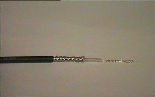
Thin coaxial cable [RJ-58AU], as used in ethernet LAN's, looks like

The connectors used in thin-net Ethernet LAN's are T connectors (used to join cables together and attach to workstations) and terminators (one at each end ofthe cable). The T-connectors and terminators look like

Fibre Optic
The features of fibre-optic cable systems
-are expensive
-used for backbones or FDDI rings (100MB/s)
-high capacity
-immune to electro magnetic interference
-low loss
-difficult to join
-connectors are expensive
-long distance

Fibre optic is often used to overcome distance limitations. It can be used tojoin two hubs together, which normally could not be connected due to distancelimitations. In this instance, a UTP to Fibre convertor is necessary.

Fibre obtic cable looks like

In addition, fibre optic patch panels are used to interconnect fibre cables. These patch panels look like


NETWORK SEGMENTS
A network segment
-is a length of cable
-devices can be attached to the cable
-it has its own unique address
-it has a limit on its length and the number of devices which can be attached to it

Large networks are made by combining several individual network segments together, using appropriate devices like routers and/or bridges.

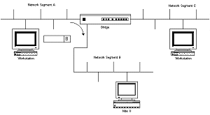
When network segments are combined into a single large network, paths exist between the individual network segments. These paths are called routes, and devices like routers and bridges keep tables which define how to get toa particular path. When a packet arrives, the router/bridge will look at thedestination address of the packet, and determine which network segment thepacket is to be transmitted on in order to get to its destination.

the above diagram, a packet arrives whose destination is segment B. The bridge forwards this incoming packet from segment A to the B segment.


SPANNING TREE ALOGRITHM
Switches and bridges generally learn about the segments they are connected to.As packets arrive, they build up a table which lists the network address used on the various network segments.

Sometimes, a loop would be created which caused the wrong packets to be sent on incorrect segments. These packets could loop around the network, being forwardedon, eventually arriving back, only to be forwarded on, etc. This quickly floodsthe network.The spanning tree algorithm is a software algorithm which defines how switchesand bridges can communicate and avoid network loops.

Packets are exchanged between bridges/switches, and they establish a singlepath for reaching any particular network segment. This is a continous process,so that if a bridge/switch fails, the remaining devices can reconfigure therouting tables to allow each segment to be reached.

To be effective, ensure that the bridges/switches in use in your network supportthis protocol.


REPEATERS
Repeaters connect multiple network segments together. They amplify the incomingsignal recieved from one segment and send it on to all other attached segments.This allows the distance limitations of network cabling to be extended. Thereare limits on the number of repeaters which can be used. The repeater counts as a single node in the maximum node count associated with the ethernet standard [30 for thin coax].

Repeaters also allow isolation of segments in the event of failures or faultconditions. Disconnecting one side of a repeater effectively isolates theassociated segments from the network.

Using repeaters simply allows you to extend your network distance limitations. It does not give you any more bandwidth or allow you to transmit data faster.

It should be noted that in the above diagram, the network number assigned tothe main network segment and the network number assigned to the other side of the repeater are the same. In addition, the traffic generated on one segment is propagated onto the other segment. This causes a rise in the total amount of traffic, so if the network segments are already heavily loaded, its not a good idea to use a repeater.

Summary of features

  1. increase traffic on segments

  2. have distance limitations

  3. limitations on the number that can be used

  4. propagate errors in the network

  5. cannot be administered or controlled via remote access

  6. cannot loop back to itself (must be unique single paths)

  7. no traffic isolation or filtering


BRIDGES
Originally designed to interconnect ethernet segments together. Most bridgestoday support filtering and forwarding, as well as Spanning Tree Algorithm. The IEEE 802.1D specification is the standard for bridges.

During initialisation, the bridge learns about the network and the routes. Packets are passed onto other network segments based on the MAC layer. Each time the bridge is presented with a frame, the source address is stored. Thebridge builds up a table which identifies the segment to which the device islocated on. This internal table is then used to determine which segment incoming frames should be forwarded to. The size of this table is important, especially ifthe network has a large number of workstations/servers.

The advantages of bridges are

  • increase the number of attached workstations and network segments

  • since bridges buffer frames, it is possible to interconnect differentsegments which use different MAC protocols

  • since bridges work at the MAC layer, they are transparent to higher levelprotocols

  • by subdividing the LAN into smaller segments, this increases overall reliability, and makes the network easier to maintain

The disadvantages of bridges are

  • the buffering of frames introduces network delays

  • bridges may overload during periods of high traffic

  • bridges which combine different MAC protocols require the frames to bemodified before transmission onto the new segment. This causes delays

Transparent bridges (also known as spanning tree, IEEE 802.1 D) make all routing decisions. The bridge is said to be transparent (invisible) to the workstations. The bridge will automatically initialize itself and configure itsown routing information after it has been enabled.

Bridges are ideally used in environments where there a number of well definedworkgroups, each operating more or less independant of each other, with occassional access to servers outside of their localised workgroup or network segment. Bridges do not offer performance improvements when used in diverse or scattered workgroups, where the majority of access occurs outside of the local segment.

The diagram below shows two separate network segments connected via a bridge. Note that each segment must have a unique network address number in order for the bridge to be able to forward packets from one segment to the other.

Ideally, if workstations on network segment A needed access to a server, the best place to locate that server is on the same segment as the workstations, as this minimises traffic on the other segment, and avoids the delay incurred by the bridge.

Summary of features

  1. operate at the MAC layer (layer 2 of the OSI model)

  2. can reduce traffic on other segments

  3. broadcasts are forwarded to every segment

  4. most allow remote access and configuration

  5. often SNMP enabled

  6. loops can be used (redundant paths) if using spanning tree algorithm

  7. small delays introduced

  8. fault tolerant by isolating fault segments and reconfiguring paths in the event of failure

  9. not efficient with complex networks

  10. redundant paths to other networks are not used (would be useful if the major path being used was overloaded)

  11. shortest path is not always chosen by spanning tree algorithm


ROUTERS
Packets are only passed to the network segment they are destined for. They work similar to bridges and switches in that they filter out unnecessary network traffic and remove it from network segments. Routers generally work at the protocol level.

Routers were devised in order to separate networks logically. For instance, aTCP/IP router can segment the network based on IP subnets. Filtering at thislevel (on IP addresses) will take longer than that of a bridge or switch whichonly looks at the MAC layer.

Most routers can also perform bridging functions. A major feature of routers, because they can filter packets at a protocol level, is to act as a firewall. This is essentially a barrier, which prevents unwanted packets either entering or leaving the network.

Typically, and organisation which connects to the Internet will install a router as the main gateway link between their network and the outside world. Byconfiguring the router with access lists (which define
what protocols and what hosts have access) this enforces security by restricted (or allowing) access to either internal or external hosts.

For example, an internal WWW server can be allowed IP access from external networks, but other company servers which contain sensitive data can be protected, so that external hosts outside the company are prevented access (you could even deny internal workstations access if required).

Summary of features

  1. use dynamic routing

  2. operate at the protocol level

  3. remote administration and configuration via SNMP

  4. support complex networks

  5. the more filtering done, the lower the performance

  6. provides security

  7. segment networks logically

  8. broadcast storms can be isolated

  9. often provide bridge functions also

  10. more complex routing protocols used [RIP, IGRP, OSPF]

HUBS
Provide full bandwidth to each client, unlike BUS networks where the bandwidth is shared. Often include buffering of packets, and filtering, so that unwanted packets (or packets which contain errors) are discarded.

In standard ethernet, all stations are connected to the same network segment inbus configuration. Traffic on the bus is controlled using the CSMA protocol, andall stations share the available bandwidth.

Hubs dedicate the entire bandwidth to each port (workstation). Theworkstations attach to the hub using UTP. The hub provides a number of ports, which are logically combined using a single backplane, which often runs at amuch higher data rate than that of the ports.

Ports can also be buffered, to allow packets to be held in case the hub or portis busy. And, because each workstation has their own port, they do not contendwith other workstations for access, having the entire bandwidth available fortheir exclusive use.

The ports on a hub all appear as one single ethernet segment. In addition, hubs can be stacked or cascaded (using master/slave configurations) together, to add more ports per segment. As hubs do not count as repeaters, this is a better option for adding more workstations than the use of a repeater.

Hub options also include an SNMP (Simple Network Management Protocol) agent. This allows the use of network management software to remotely administer and configure the hub. Detailed statistics related to port usage and bandwidth are often available, allowing informed decisions to be made concerning the state of the network.

In summary, the advantages of hubs are,

  • each port has exclusive access to its bandwidth (no CSMA/CD)

  • hubs may be cascaded to add additional ports

  • SNMP managed hubs offer good management tools and statistics

  • utilize existing cabling and other network components

  • becoming a low cost solution


ETHERNET SWITCHES
Ethernet switches increase network performance by decreasing the amount of extraneous traffic on individual network segments attached to the switch. They also filter packets a bit like a router does.

When a packet arrives, the header is checked to determine which segment the packet is destined for, and then its forwarded to that segment.If the packet is destined for the same segment that it arrives on, thepacket is dropped and not retransmitted. This prevents the packet being"broadcasted" onto unnecessary segments, reducing the traffic.

Nodes which inter-communicate frequently should be placed on the same segment. Switches work at the MAC layer level.

Cut-Through Switches
-only the first few bytes of the packet is read to obtain the source and destination addresses
-the packets are then passed through to the desination segment without checking the rest of the packet for errors
- invalid packets can still be passed onto other segments
- there is little delay involved in packet throughput

Cut through switches use either a cross-bar or cell-backplane architechure.

Cross-bar switches
--read the destination address then immediately forward
--acts as a simple repeater once the path is established
--can introduce delay, if the destination port is busy, it may need to bufferthe packet
Cell-backplane switches
--break the frame into small fixed cell lengths
--each cell is labelled with special headers which contain the address(s) ofthe destination port

--the cells are buffered at the destination port
--the cells are then reassembled and transmitted
--the data rate on the backplane is significantly greater than the aggregatedata rate of the ports
--in heavily overloaded networks, cell-backplane switching offers better performance than cross-bar switching

Store-Forward Switches
--they examine the entire packet
--each incoming packet is buffered, then examined
--the switch filters out any bad packets it detects
--good packets are forwarded to the correct segment
--detect more errors than the cut-through variety
--impose a small delay in packet throughput


Other Forms of Ethernet

  • FOIRL [Fibre over inter repeater links]
    -user to connect repeaters together in order to get greater distances
    -maximum of 1Km

  • 10BaseF
    -fibre to desktop
    -applies to 10Mbps CSMA/CD
    -star network topology
    -Comprised of 10BaseFB, 10BaseFL, 10BaseFP

  • 10BaseFB Synchronous Backbone
    -also known as 10BaseFA
    -2Km per segment
    -30 repeater hops allowed
    -no connection to desktop computers

  • 10BaseFL Asynchronous Active
    -also known as 10BaseFF
    -connects repeaters to DTE's
    -FOIRL compatible
    -2Km segment

  • 10BaseFP Passive
    -passive star topology
    -non FOIRL compatible
    -1Km segments


100 Megabit Ethernet

  • 100Base-X
    Comes from Grand Junction Networks, supported by companies like
    3Com, Intel and Sun Microsystems. This is backward compatible with 10Mbps ethernet, and uses the CSMA/CD protocol. It is designed to work using the existing cable types.

Summary of features
--based on ANSI FDDI over copper
--uses MLT-3 signalling
--retains CSMA/CD
--uses two pairs
--uses ethernet packet format
--requires no changes to exisiting network components, cabling, bridges
--need category 5 cabling

  • 100Base-VG (Voide Grade)
    Designed by Hewlett Packard and AT&T, allows users to assign priority to packets (normal or high). It increases the bandwidth from 10Mbps to 100Mbps.CSMA is not supported, instead, a
    proprietary technique called quadrature signaling and demand priority is used.
    All four pairs are used to send the packet to a hub. If more than one packet arrives at the hub at the same time, the highest priority packet is servicedfirst. Typically use VIDEO with high priority Ethernet Frame - yes CSMA/CD - no Voice grade UTP - yes Uses two-level NRZ output, 5 data bits converted into 6 transmit bits. Half-duplex.

Summary of features
--uses voice grade cable
--supported by Microsoft, Apple, Novell, etc
--signal is split over 4 pairs
--data is half duplex, one direction at a time
--handles time sensitive data like voice and video
--CSMA/CD replaced with Demand Priority Protocol

  • 100BaseT
    This is an extension of the existing ethernet standard.
    --100BaseTX uses two-pair Category 5 UTP/STP cabling
    --100BaseT4 uses four-pair Category 3, 4 or 5 UTP cabling
    --100BaseFX uses two-strand fiber

In order to achieve the high 100Mbps rate, the collision timing associated with CSMA/CD is reduced. This means the total lengths of cabling from a workstation to another via two hubs cannot exceed 205 meters. If using fiber, a maximum distance of 405 meters from workstation to hub is allowed.

100BaseT devices are auto sensing, which means they can run at either speed. On startup, the card advertises their speed with a series of Fast Link Pulses. If a hub supports this, it will detect the FLP's, and then negotiate with the card for the highest possible speed. This can be over-ridden by network managers, who can force the slower 10Mbps mode.

Summary of features
--supported by Sun, Synoptics and 3Com
--uses CSMA/CD
--uses ethernet frame format
--uses new signalling scheme using 3 voltage levels

  • 100Base-VG-AnyLAN
    IBM and HP have worked together to expand the 100Base-VG specification to include token ring. This will support Cat3, type4 and Type5 cable. It will not require any changes to existing wiring or to bridges and routers.

  • The advantages of 100BaseVG-AnyLan over 100BaseT are,
    --its topology is not so limiting
    --traffic can be prioritized, giving better response to some users who need it
    --better suited to video and voice data